The brief
For the semester-long Rapid Design and Assembly Challenge, our team set out to vary the tactile force of a keyboard. The concept was motivated by the discomfort that can come with repetitive typing; this classroom prototype explored a changeable typing feel rather than testing a medical outcome.
I led the team and took responsibility for programming and design. We had ten weeks and a $100 budget to develop, assemble, demonstrate, and pitch a working prototype.
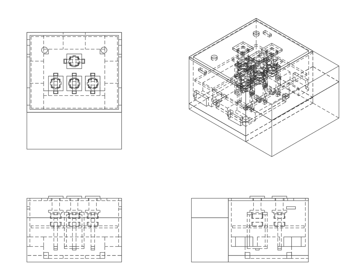
Magnetic mechanism
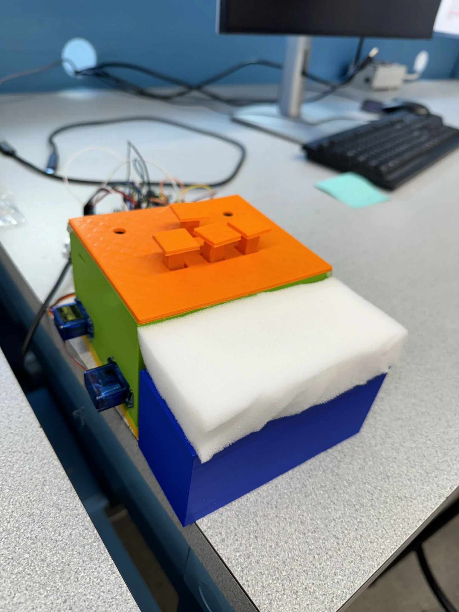
Each key used a pair of facing, repelling magnets: one in the moving key and one on a plate below it. Changing the plate height with servos changes the separation between the magnets and the force needed to press a key. A foam wrist rest was added to the physical assembly.
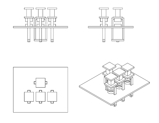
Electronics & build
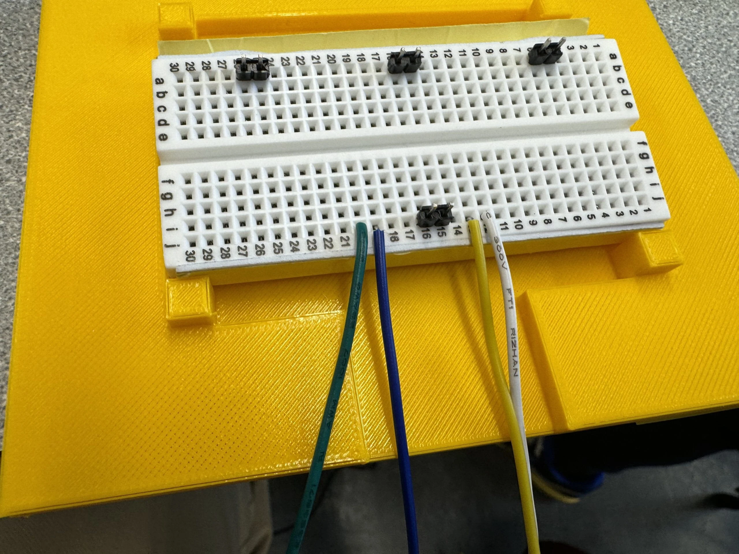
We wired the keys as a matrix to limit the number of Arduino pins needed. In the prototype, metal contacts beneath the keycaps registered the presses. Two potentiometers controlled servo position and the repeated keystroke rate, while a buzzer signaled the servo travel limit.
The physical model used four WASD keys so the team could test the mechanism, wiring, and typing response within the course constraints.
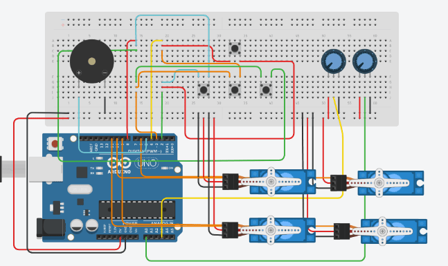
Code & controls
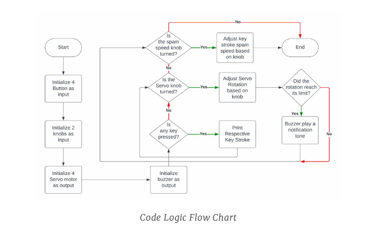
I developed the Arduino control logic around the four key inputs, two adjustment knobs, servos, and buzzer. The program detects key presses and sends the corresponding keystrokes. One knob changes the servo position and therefore the magnet gap; the other adjusts the repeated keystroke rate. When the servos reach their travel limit, the buzzer provides feedback.
The flowchart shows how the program initializes the inputs and outputs, checks the controls, and responds to a key press or limit condition.
Demo & outcome
The team completed the course benchmarks, three milestone demonstrations, and commissioning, then delivered and pitched the prototype to faculty. The video below shows the team explaining the concept and demonstrating the assembled device.
A first-year NYU RAD team project completed in Fall 2023.