The challenge
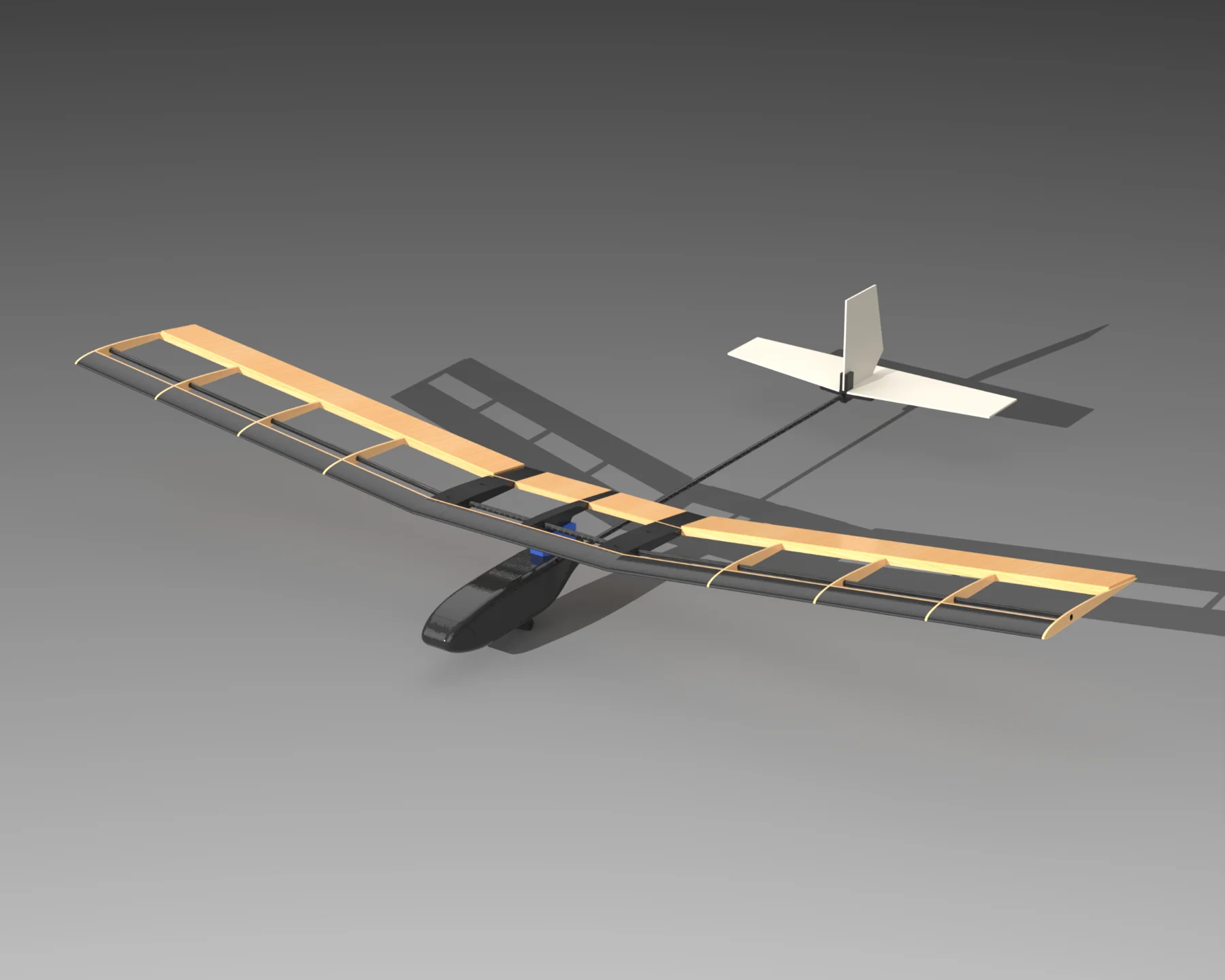
The glider needed to fly steadily and efficiently, carry an active control system, and fit into a 70 × 45 × 30 cm suitcase for travel. Those requirements drove the removable wing, low-mass structure, and careful placement of the center of gravity.
I worked across aerodynamic sizing, CAD, fabrication, electronics integration, control calibration, and flight testing with my teammate and Nagoya University’s laboratory staff.
| Main wing | 1.00 m span × 0.160 m chord; 0.16 m² area |
|---|---|
| Aspect ratio / airfoil | 6.25 / AG03 |
| Preliminary target mass | 220 g; completed glider approximately 340 g |
| Target center of gravity | 30% of chord from the wing leading edge |
Why AG03?
At the preliminary 220 g target mass and assumed 6 m/s flight speed, the design called for a lift coefficient of about 0.62 at Reynolds number 64,000. AG03 was chosen from low-Reynolds-number airfoil polar comparisons. The heavier final aircraft would require more lift at the same speed.
Airframe design
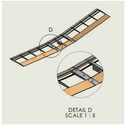
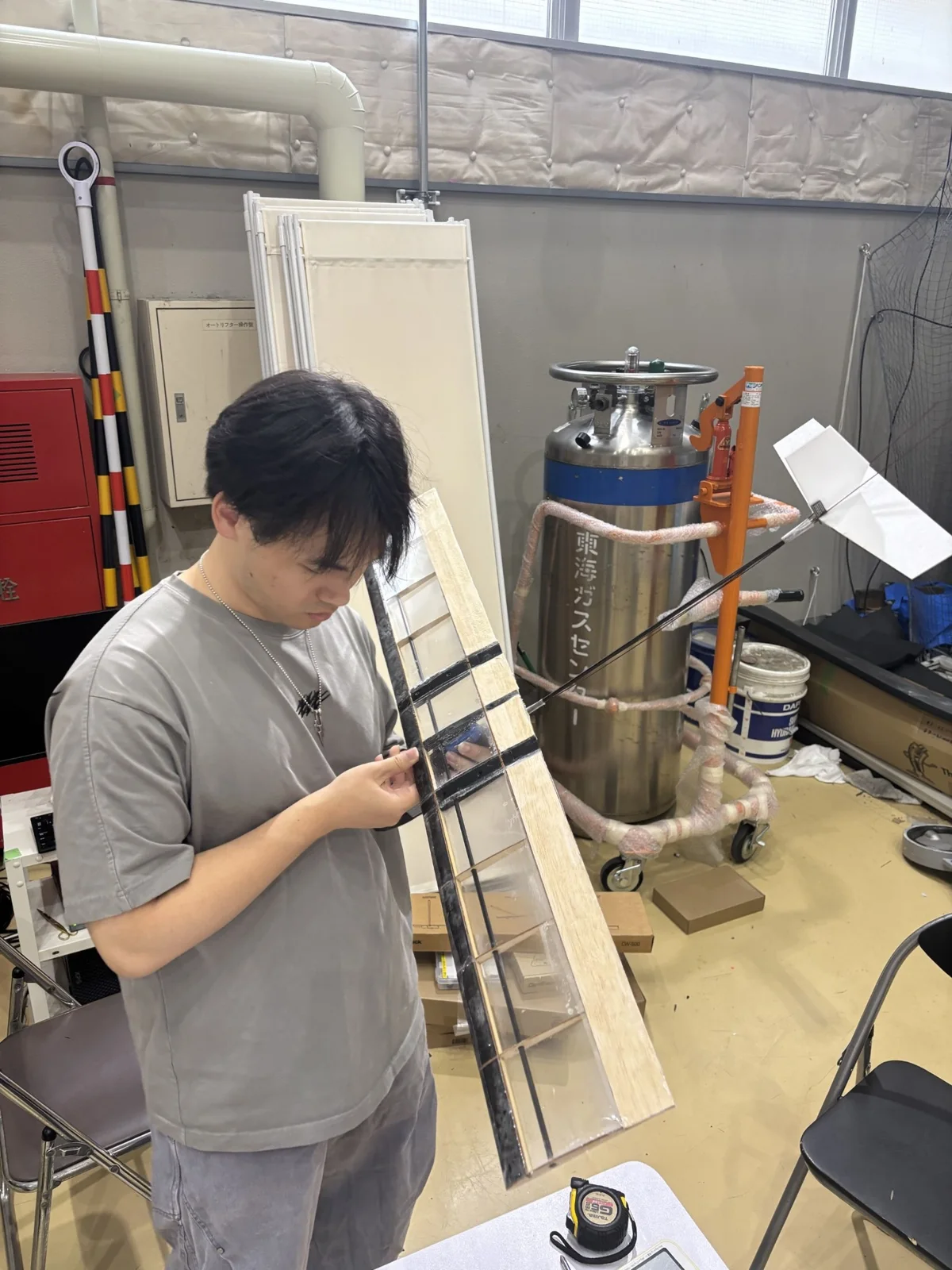
The 1 m wing separates into a 0.2 m center panel and two 0.4 m outer panels so the aircraft can be packed. The outer panels have 7° dihedral for passive roll stability. A carbon-fiber spar stiffens the wing, while a carbon-fiber boom supports the tail at about a 0.5 m moment arm.
At the center joint, countersunk M3 fasteners and captured hex-nut pockets hold the panels in alignment and allow repeated assembly. A foam tail reduced weight behind the wing, where added mass made balancing more difficult.
Build & integration
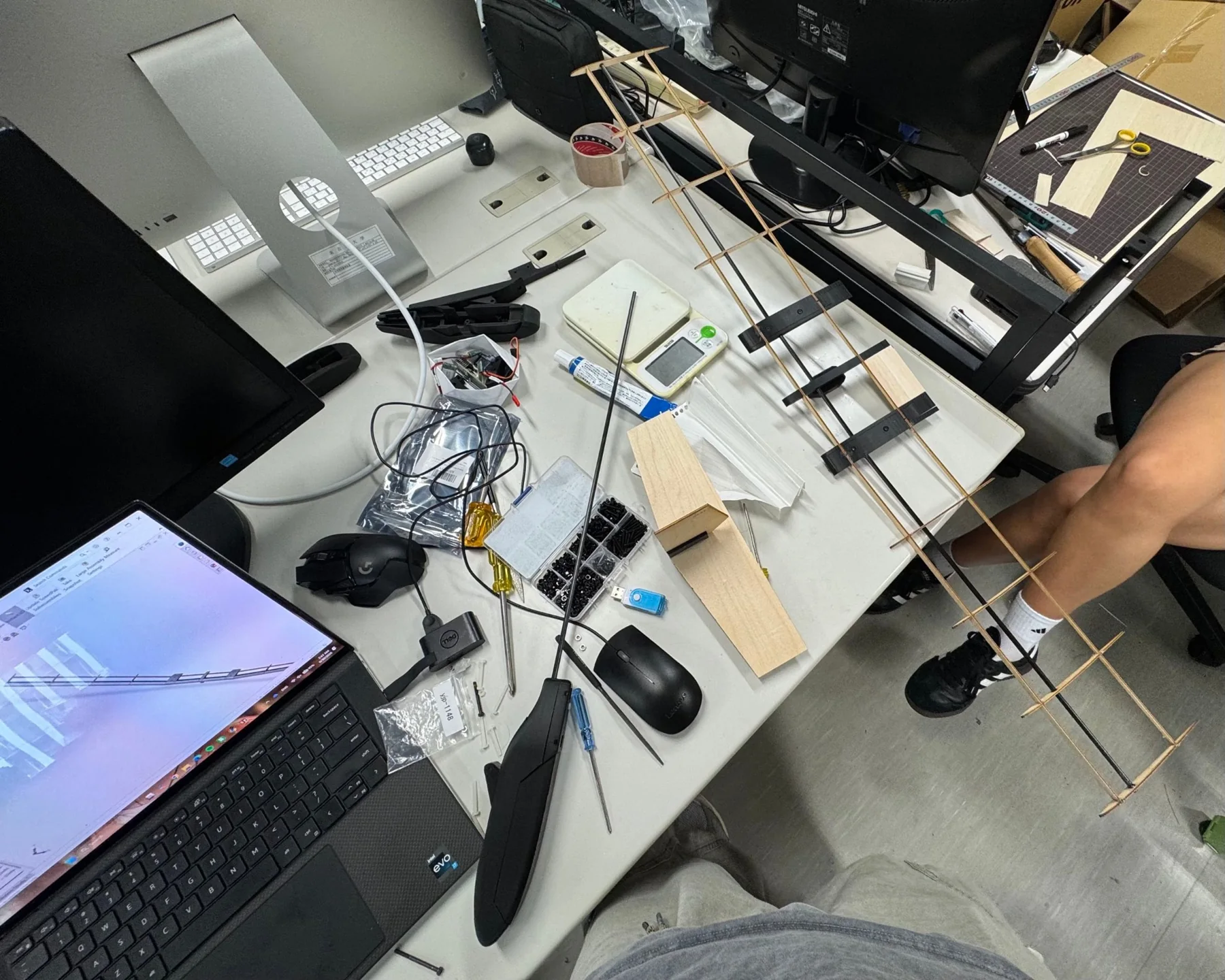
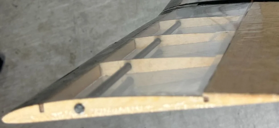
Laser-cut birch ribs at 10 cm spacing formed the wing section around the spar. PLA printed parts handled the nose housing and angled connections. After test-fitting joints, bolt holes, and spar openings, we assembled the frame and applied heat-shrink film over the wing.
Flight control
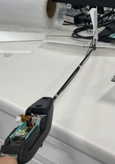
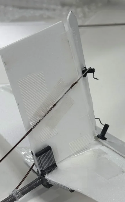
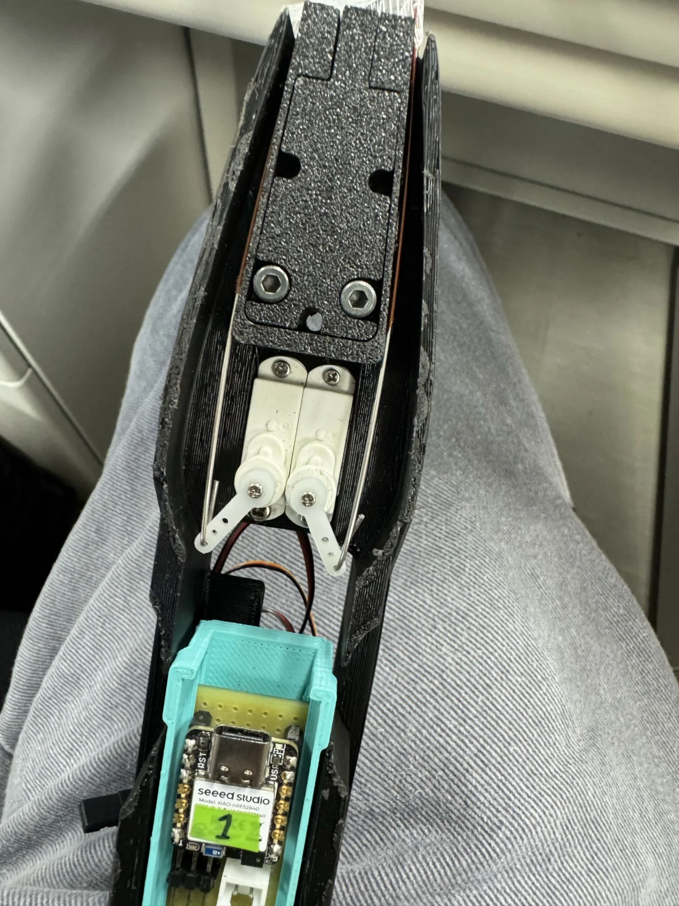
A Seeed XIAO nRF52840 Sense reads its six-axis IMU. A Madgwick filter estimates roll and pitch, then proportional feedback commands the elevator and rudder through servos and steel pushrods. The launch attitude sets the reference; servo travel is limited in software to protect the linkage.
The rudder provides roll correction through the wing’s dihedral effect. The six-axis IMU does not provide an absolute yaw reference, so the system does not use direct yaw feedback.
Test & iterate
Indoor launches used a rubber-band guide to repeat the release. The first configuration weighed about 380 g, had a balsa tail, and placed the center of mass roughly 8 cm behind the intended 30%-chord location. It pitched up sharply and stalled.
We replaced the tail with lighter foam, reduced PLA infill, and moved the center of mass forward. The revised glider weighed about 340 g. Later tests enabled proportional feedback, tuned pitch and roll gains, and compared wing-incidence settings; 3° produced the most stable glide. Because several changes were made together, the improvement cannot be assigned to the controller alone.
Competition & lessons
At Gifu University on July 10, 2026, the glider completed a best flight of approximately 35 m on the third of five launch attempts. This was the longest flight achieved in the first three years of the SILP glider program. It remained stable through most of the flight before turning as it slowed.
Later attempts exposed a launch-system integration problem: a thin release string caught around the tail and damaged its structure and linkage. A future revision would protect the pushrods, increase string clearance, and reinforce the foam tail. The testing also showed how important mass distribution and launch compatibility are to a working control system.
Project completed with Sofia Pacheco and support from Prof. Susumu Hara, laboratory teaching assistants, and students at Nagoya University.