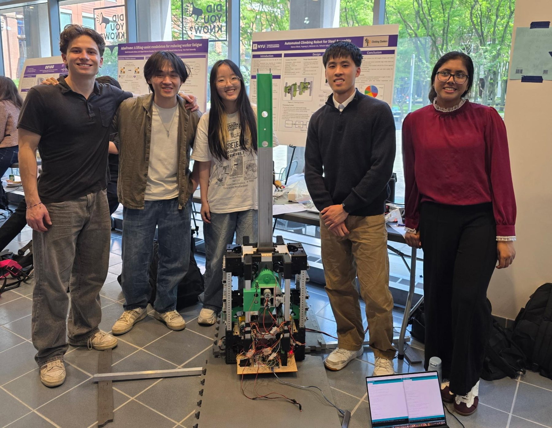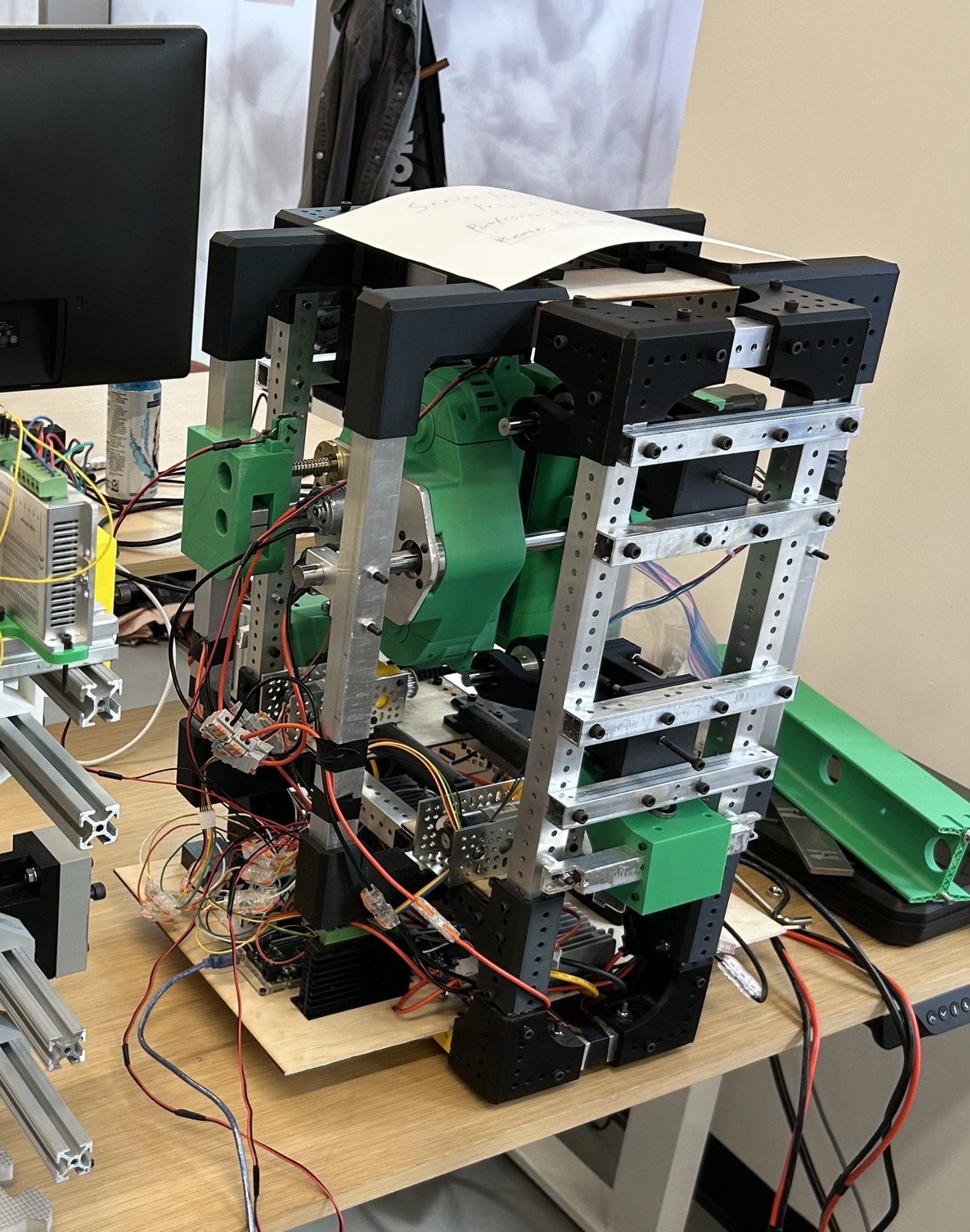
The system
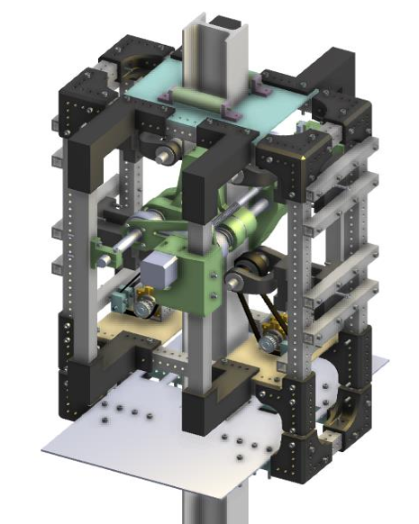
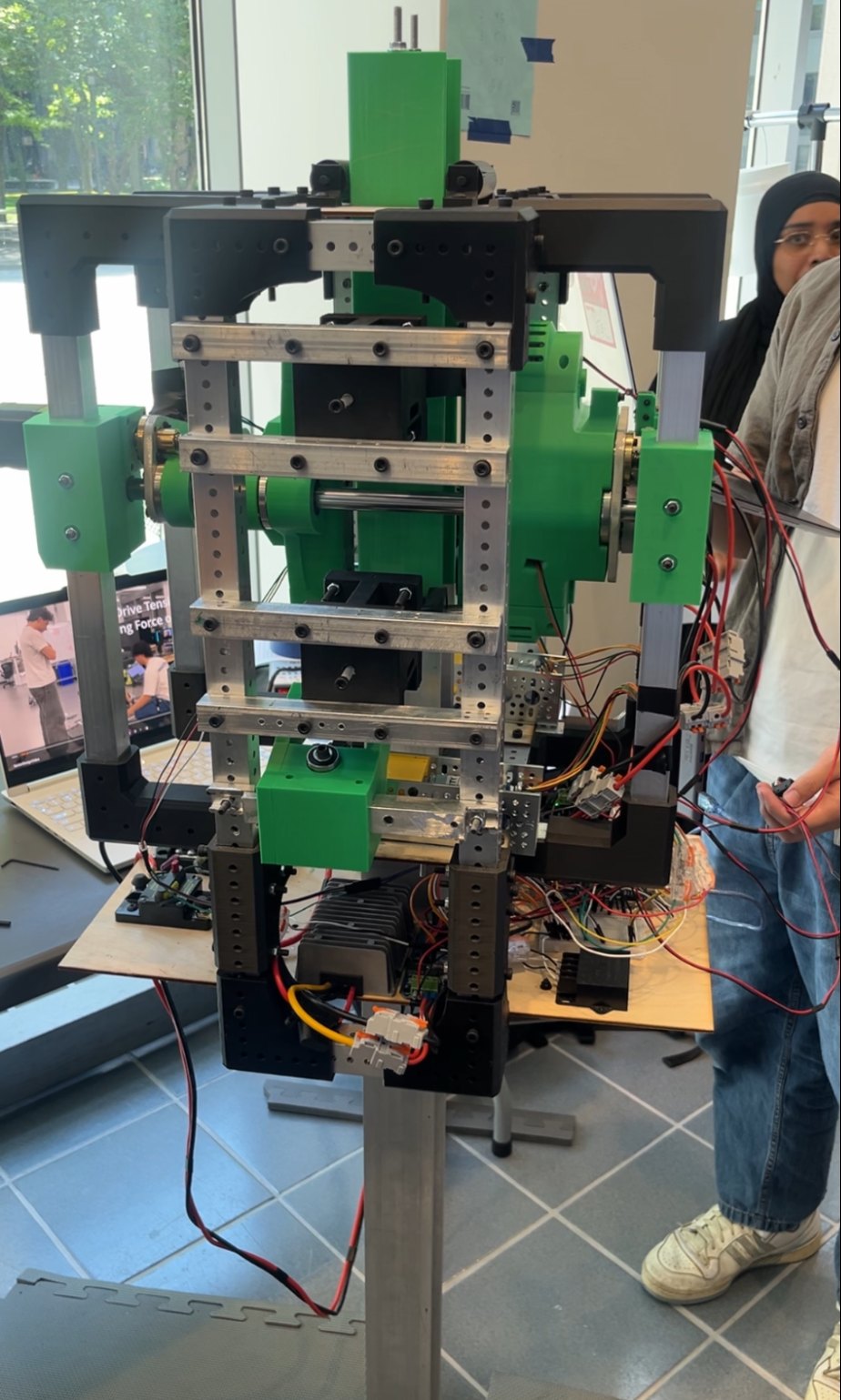
Installing splice plates high on steel columns exposes workers to difficult positioning and fastening tasks. Our senior design prototype explored a way to move the fastening operation onto a climbing robot. Spring-loaded wheel modules grip a vertical I-beam; a dual-spindle mechanism positions and drives two fasteners into a plate.
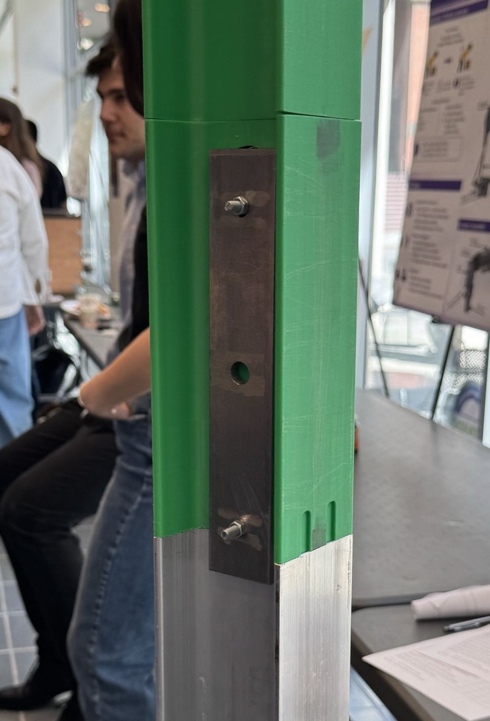
The full robot combined locomotion, a plate and nut feeding mechanism, a structural frame, sensors, and an electrical system. I worked across the electrical and mechanical integration needed to turn those subsystems into a testable machine. In a fall 2025 ANSYS study, I modeled eigenvalue buckling of the bolted I-beam column as additional 3 ft segments were assembled. Under a 50 lbf reference load and a factor-of-safety target of 3, the model supported a recommended height of 24 ft (eight segments, seven joints). This was a preliminary analysis of the column under stated assumptions, not a measured limit of the finished robot.
Power & electronics
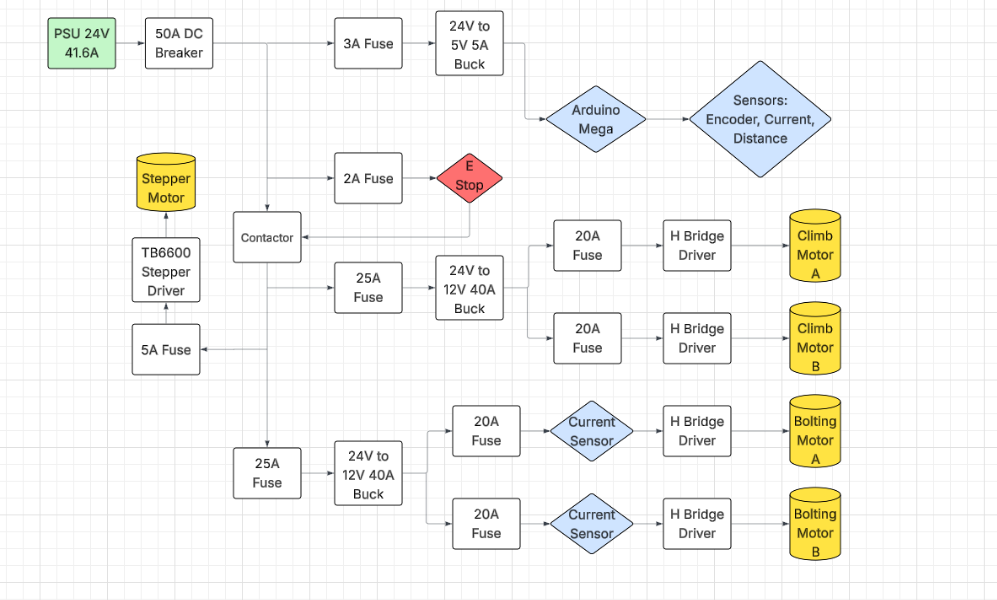
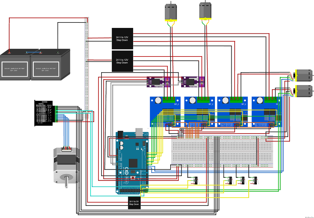
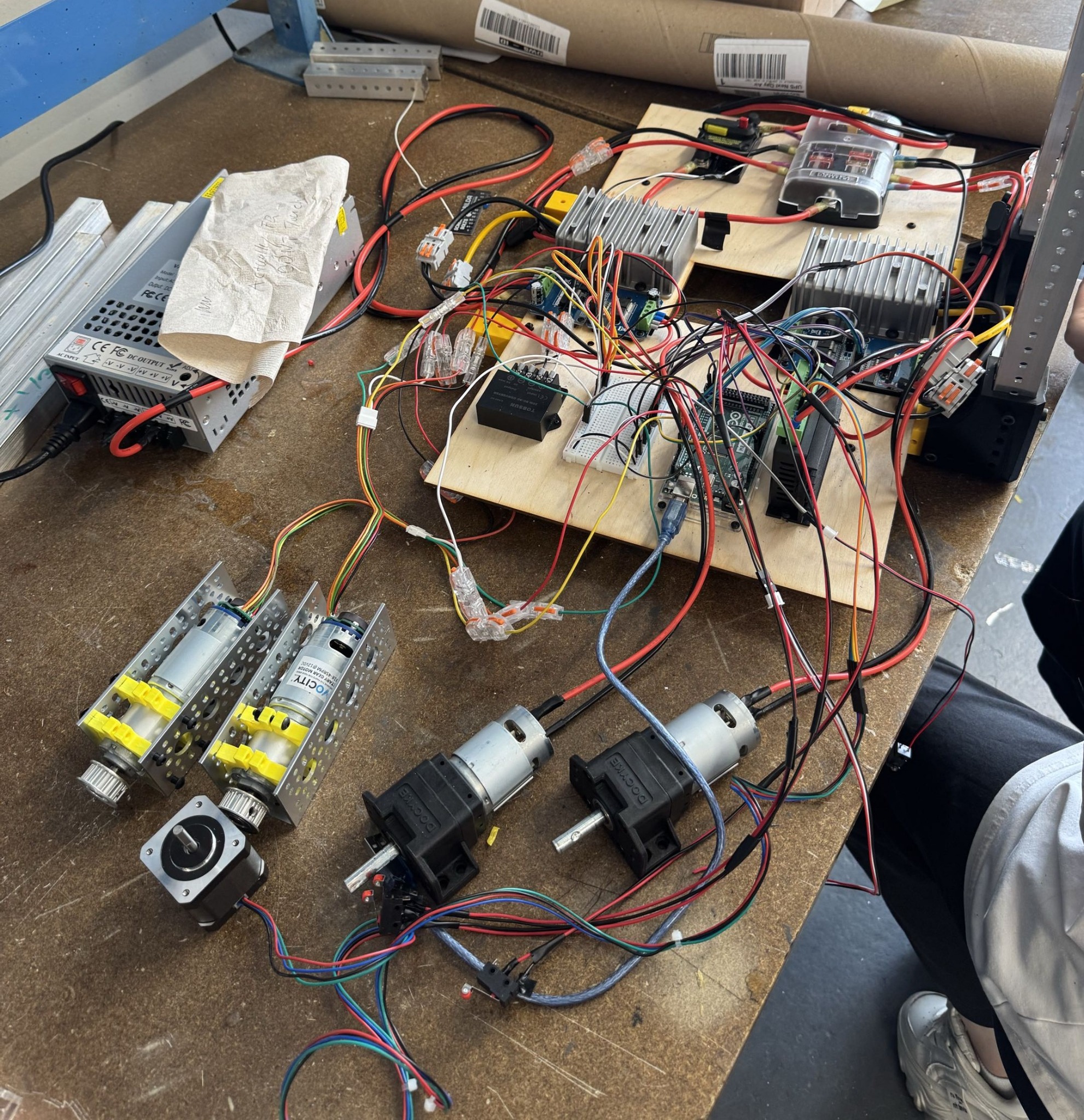
I calculated the voltage requirements, developed the power distribution approach, and integrated the electronics. The design starts with a 24 V supply and distributes power through protection and regulation to the Arduino Mega, sensors, stepper driver, and climbing and bolting motor drivers. I assembled the components on an electronics plate and installed that plate on the robot.
Building the plate meant routing power and signal wiring around the frame and checking that the drivers, controller, sensors, and motors worked together before the full climbing test.
Controls
I wrote the robot’s control code, including encoder-based PI speed control for climbing and the sequence that moves from beam positioning to fastening and return. Sensor checkpoints and the feeding stepper coordinate the operation with the two bolt-driving motors.
The team reported a 4.2 cm/s climbing speed, an approximately 85-second bolt cycle, and an approximately 2.5-minute full cycle.
- ClimbRegulate wheel speed using encoder feedback.
- LocateStop at the beam checkpoint and position the fastening assembly.
- FastenAdvance the mechanism and run the two bolt motors for the timed interval.
- ReturnRetract the mechanism and move back to the loading position.
Fastening subsystem
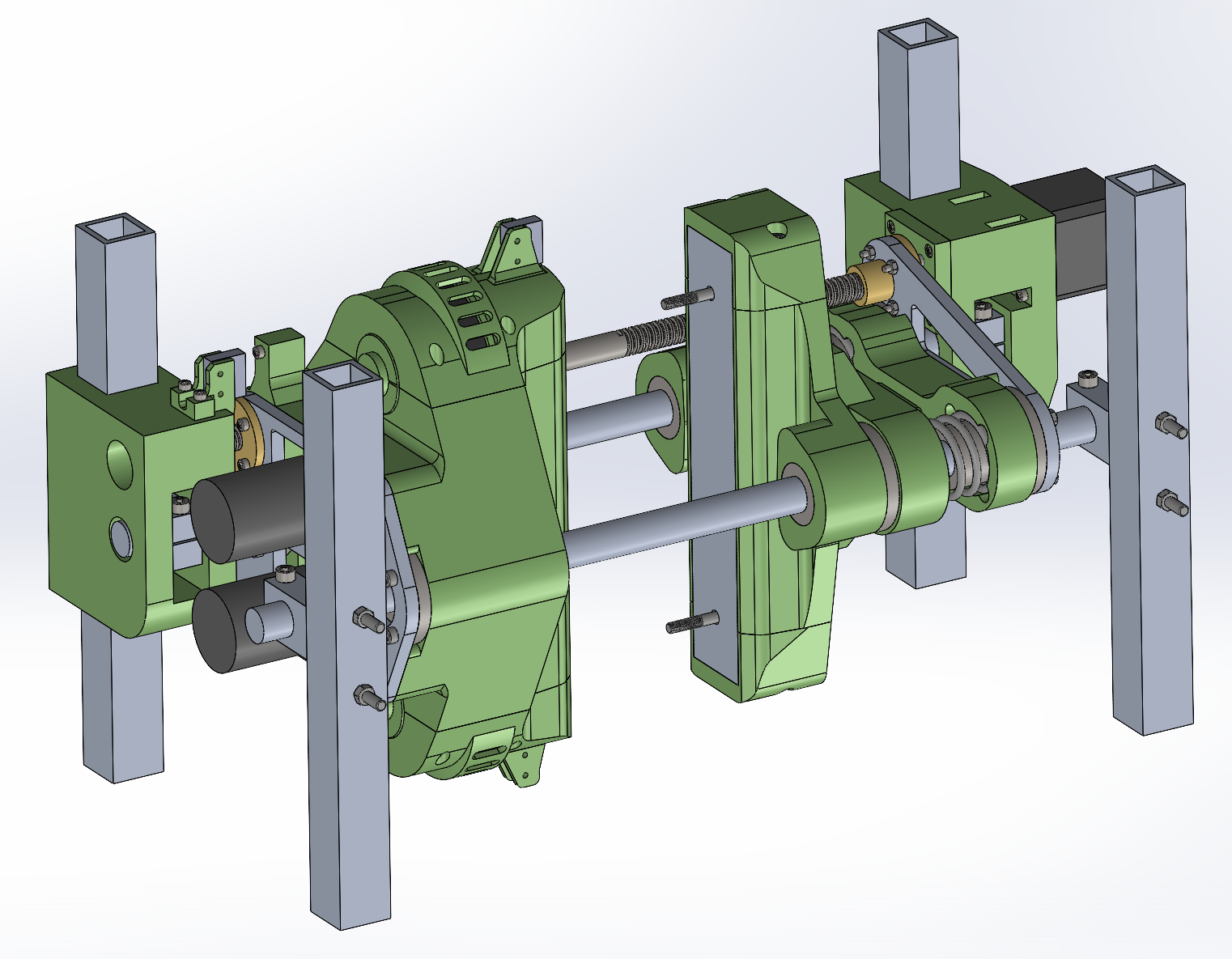
The fastening assembly brings two motor-driven spindles to the splice plate. I integrated the bolt motors and their drivers into the robot’s electrical and control sequence.
We explored current feedback for tightening, but motor operation made the current signal difficult to read reliably on the Arduino. In the final demonstrated build, the fastening motors ran for a fixed 20 seconds. The cycle did not provide a measured tightening torque.
Physical integration
I also helped build the robot’s frame and mounted the completed electronics plate to it. The physical build brought the wheel modules, fastening mechanism, I-beam clearance, power components, and wiring into one assembly that could be tested on the beam.
I organized a cost-reduction plan against the $1,000 base budget. We reused fasteners, sourced small quantities when possible, and substituted 3D-printed parts where the structural requirements allowed it. This reduced the projected build cost from about $1,900 to about $1,400, roughly 26%. I also sought supplemental support from faculty and mentors to cover the amount above the base budget.
I reviewed design revisions with teammates and supported 3D printing and assembly. The team fabricated, integrated, and tested the prototype in approximately one month during the final build period.
Testing & recognition
In six full test runs reported at the end of the project, four engaged the nuts and secured the plate to the I-beam. The prototype demonstrated climbing, holding position, and fastening. The report records stable power near 24 V and no visible frame deformation during testing.
Alignment accuracy and final bolt torque were not measured as numerical results. Belt wear, positioning, and more reliable tightening feedback remained areas for further development.
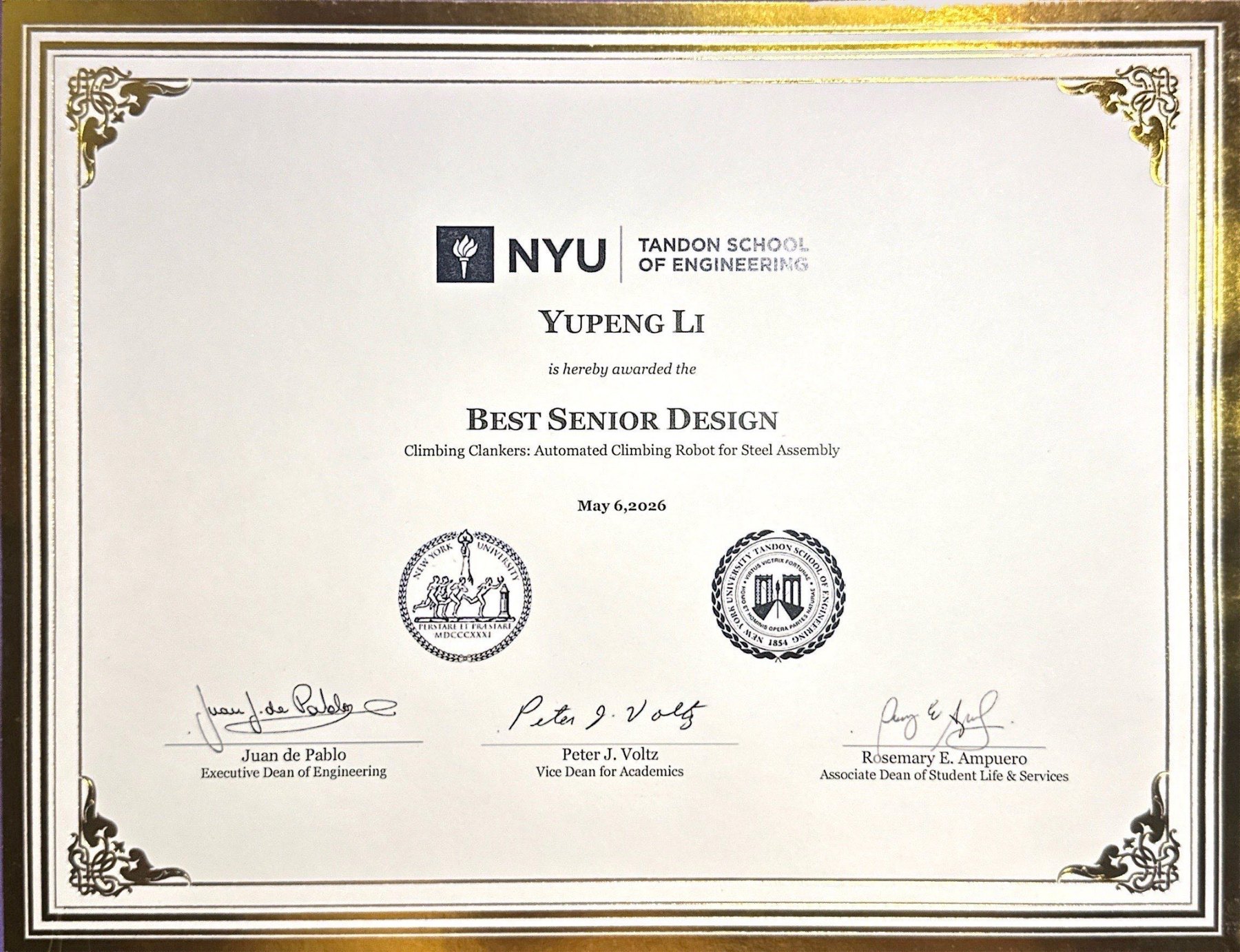
The project was awarded Best Senior Design by NYU Tandon on May 6, 2026.
Project documents
The poster records the design-stage concept and targets. The final report documents the tested prototype, including the timed fastening sequence and preliminary results.
Climbing Clankers: Henry Elliott, Yupeng Li, Melanie Lin, Tahasin Iqbal, and Jonathan Shan. Mentored by Prof. Ludovic Righetti.